
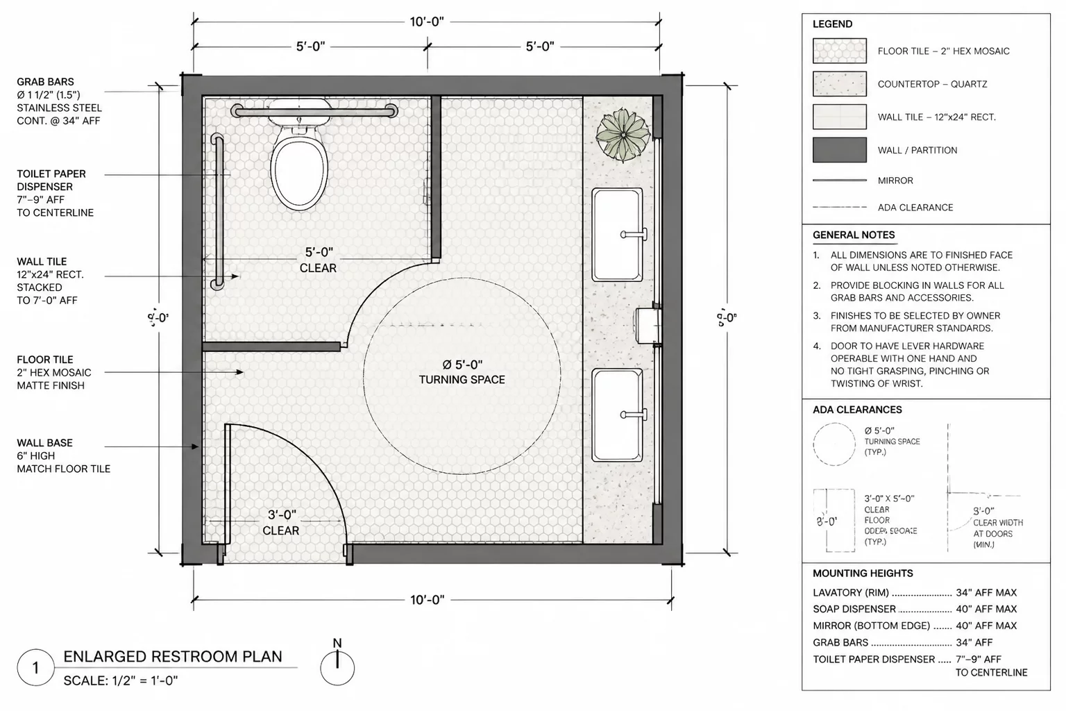
Defining Purpose in Enlarged Scale Viewports
Enlarged floor plans typically operate at 1/4" = 1'-0" (1:50) or 1/2" = 1'-0" (1:20) scales to resolve dimensional tolerances that remain invisible on general arrangement drawings. In high-density architectural spaces such as commercial restrooms, mechanical closets, and core circulation stairs, general building floor plans cannot accommodate millimeter-level trade coordination. The enlarged room plan solves this by isolating the boundary walls and zooming directly into critical assemblies.
The primary trap drafters fall into involves carrying the exact layer and class visibility settings from the 1/8" parent plan into the enlarged viewport. An effective enlarged plan requires deliberate viewport class overrides to unhide wall component hatches, backing blocking, tile setlines, and specific rough-in plumbing centerlines while suppressing broad room finishes and global grids that obstruct field dimensions.
Core Rules for Enlarged Plan Execution
-
1
Crop Boundary Tightness: Keep crop containers offset exactly 12 to 18 inches beyond perimeter room partitions to preserve structural grid tags without leaking uncoordinated adjacent rooms.
-
2
Component Hatch Threshold: Enable detailed wall and floor assembly components in Vectorworks viewport settings to show structural stud depth and gypsum board layers clearly.
-
3
Dimension Chain Separation: Separate rough opening strings from finish surface strings across distinct annotation classes to prevent contractor layout errors on site.
-
4
Elevation Callout Anchors: Place interior elevation markers directly within the enlarged plan annotation layer rather than scattering them across overall floor plans.
"An enlarged room plan is not just a magnified drawing; it is an independent contract document answering how distinct trades interface in tight construction envelopes."
Vectorworks Workflow: Class Overrides and Annotation Discipline
When creating an enlarged room viewport in Vectorworks, initiate the viewport from the design layer using a clean crop rectangle rather than duplicating an existing overall sheet viewport. Immediately enter the Viewport Properties dialog to configure Class Overrides: increase the pen weights of structural masonry and wall cores to 0.35mm while knocking down secondary equipment lines to 0.13mm with light grey tones.
Enter the Annotation space of the viewport to establish clear reference callouts. All critical rough-in dimensions—such as plumbing stub-outs, grab bar backing plates, and electrical junction boxes—must reference finished face of stud (FFS) or finished face of drywall. Use custom data tags linked to record formats to call out architectural woodwork, fixture types, and tile transitions seamlessly.
Advance Your Sheet Organization
Discover comprehensive viewport configuration standards and download ready-to-use template cards designed for Vectorworks Architect.
Frequently Asked Questions
Recommended Tutorials & Studies
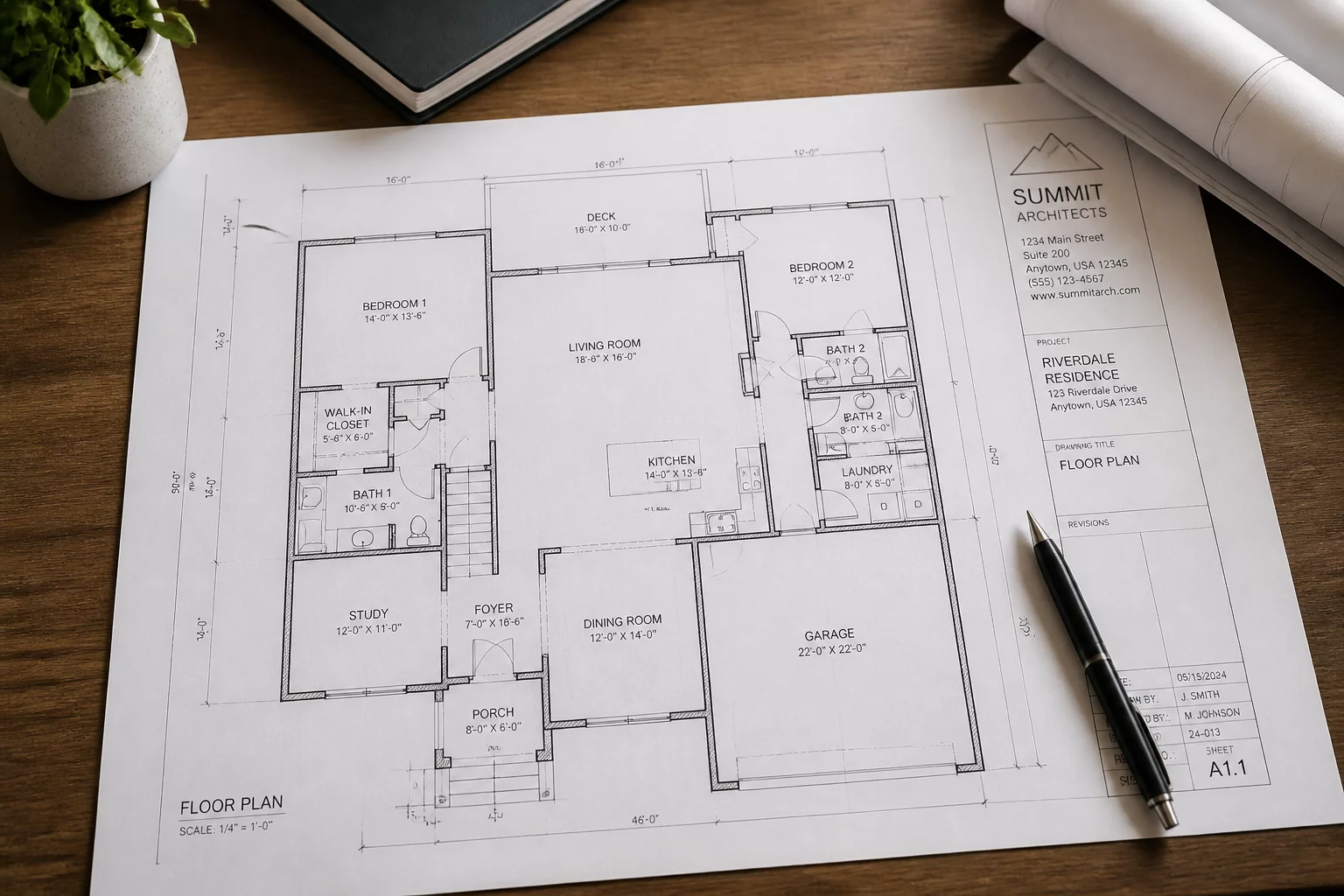 Viewport Strategy
Defining the Audience First
Learn why identifying the drawing reader is the essential first step in viewport setup.
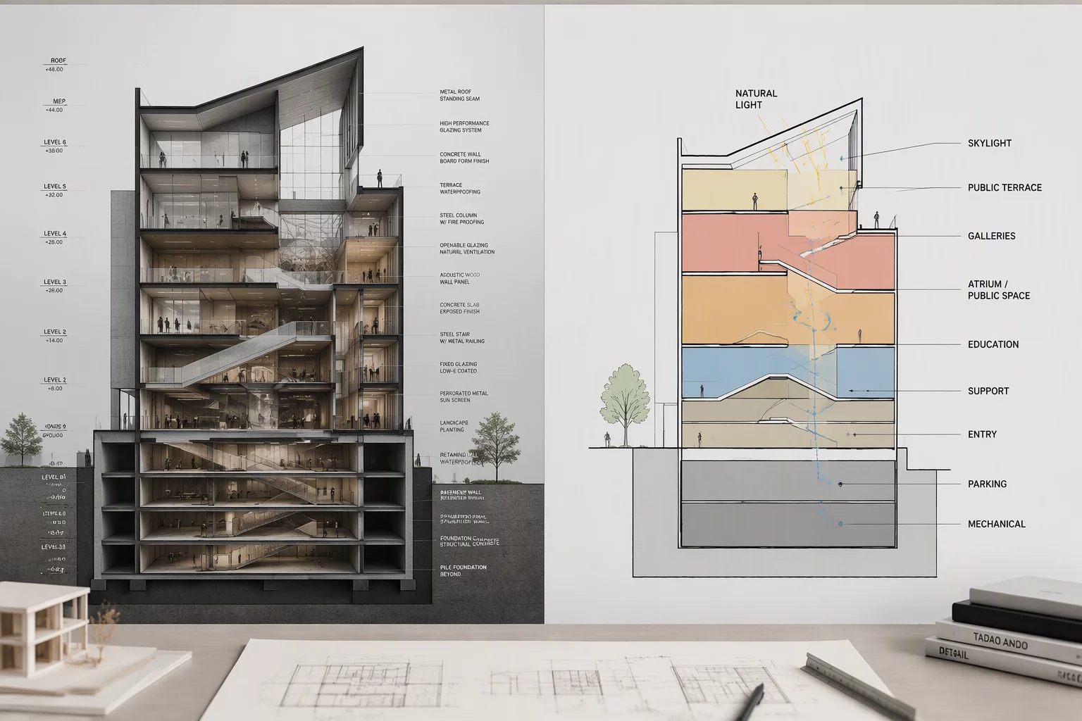 Scale Standards
Detail Level Management
Adjusting visual detail levels and component displays to match sheet drawing intent.
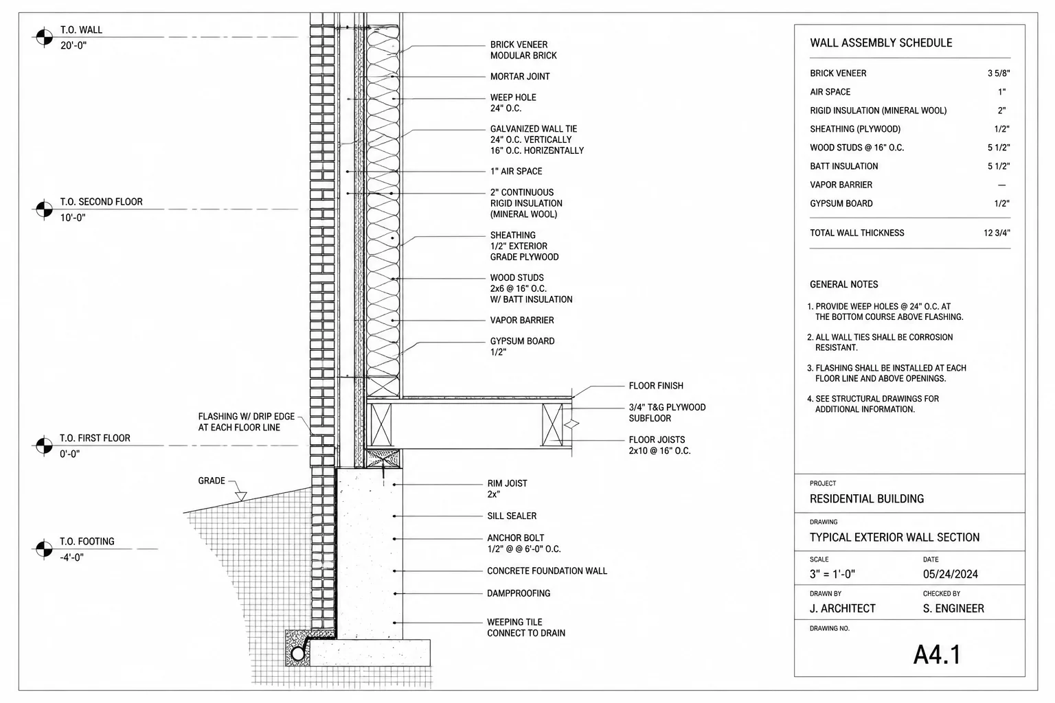 Technical Detailing
Construction Detail Intent
Ensuring technical wall sections and construction details communicate intent with zero ambiguity.