
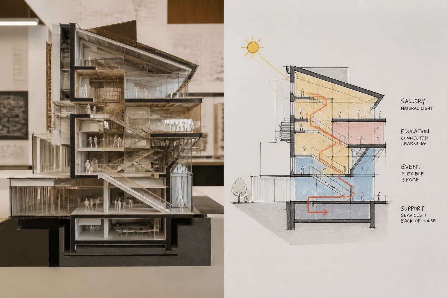
Aligning Graphic Density with Sheet Purpose
Technical drawings often fail not from lack of information, but from excessive detail that overwhelms the reader. A common mistake in building information modeling involves displaying fully resolved wall components, fasteners, and cavity insulations on 1:100 general arrangement plans. When a viewport scale reduces geometry to tight clusters of ink, lines merge, dimensions lose legibility, and contractors spend unnecessary time deciphering basic boundaries.
Detail level management establishes strict rules for how building components present themselves across varied viewport scales. In Vectorworks, components within walls, slabs, and roofs can automatically switch between Low, Medium, and High detail configurations. Establishing this hierarchy early prevents visual noise on macro plans while preserving intricate junctions for enlarged callouts.
Core Rules for Detail Level Allocation
-
1
Scale-Driven Switching: Set general arrangement plans (1:50 to 1:200) to Low detail to display only outer object boundaries and core structural definitions without internal insulation hatching.
-
2
Component Thresholds: Reserve Medium detail for enlarged room layouts (1:20 to 1:50) where finish layers and cavity depths inform trade coordination without overwhelming clearances.
-
3
Assembly Breakdowns: Activate High detail strictly on construction details (1:1 to 1:10) where flashings, membrane laps, and fixings answer specific fabrication questions.
-
4
Annotation Independence: Keep dimension strings tied to structural cores rather than superficial finish lines to maintain consistency when viewport detail settings change.
"The true measure of an architectural drawing is not how much geometry it contains, but how rapidly the reader extracts the answer to their immediate task."
Implementing Automated Display Rules in Vectorworks
Vectorworks allows users to configure component visibility directly within hybrid object styles. In wall and slab style definitions, every layer receives a detail visibility flag. Once configured, adjusting the viewport detail setting in the Object Info palette instantly recalibrates the linework across the entire sheet layer without redrawing or manual masking.
For advanced project deliverables, combining detail levels with viewport class overrides yields complete graphic control. If a code plan requires wall fire ratings to stand out, suppressing internal stud lines via detail controls while highlighting wall centerlines produces an immediate, uncluttered document for regulatory review.
Standardize Your Viewport Workflow
Access comprehensive view intent templates and viewport configuration matrices tailored for Vectorworks production sheets.
Frequently Asked Questions
Related Tutorials & Guidance
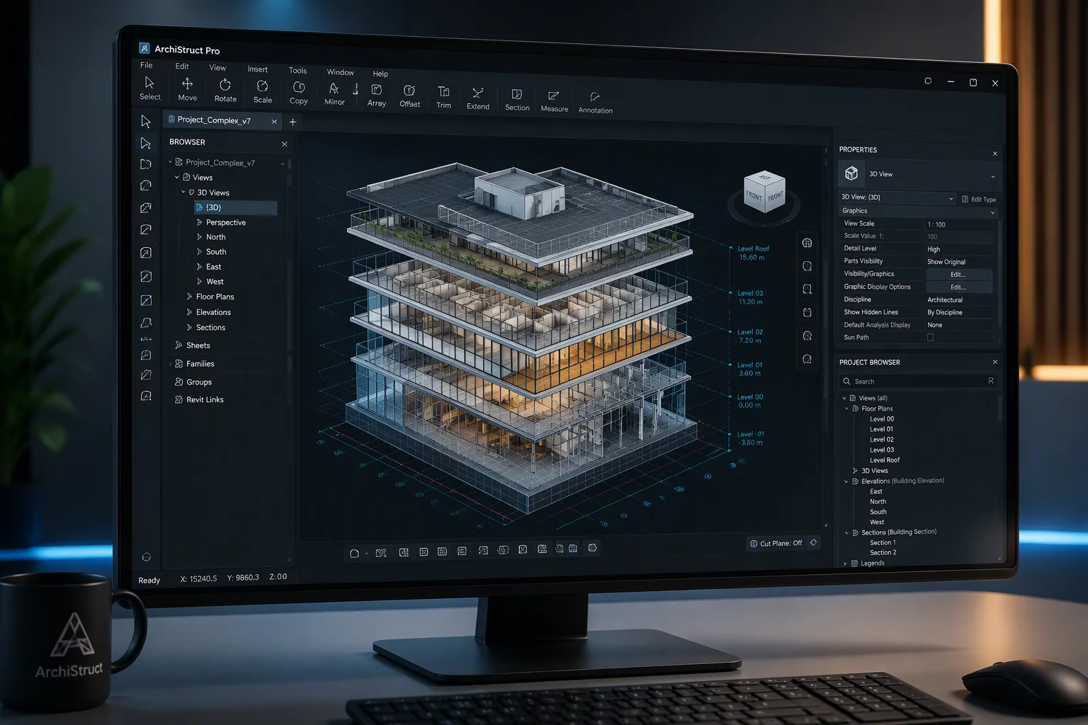 Layer Setup
Mastering Layer Visibility
Strategies for managing design layer visibility and stacking order across complex multi-sheet drawing packages.
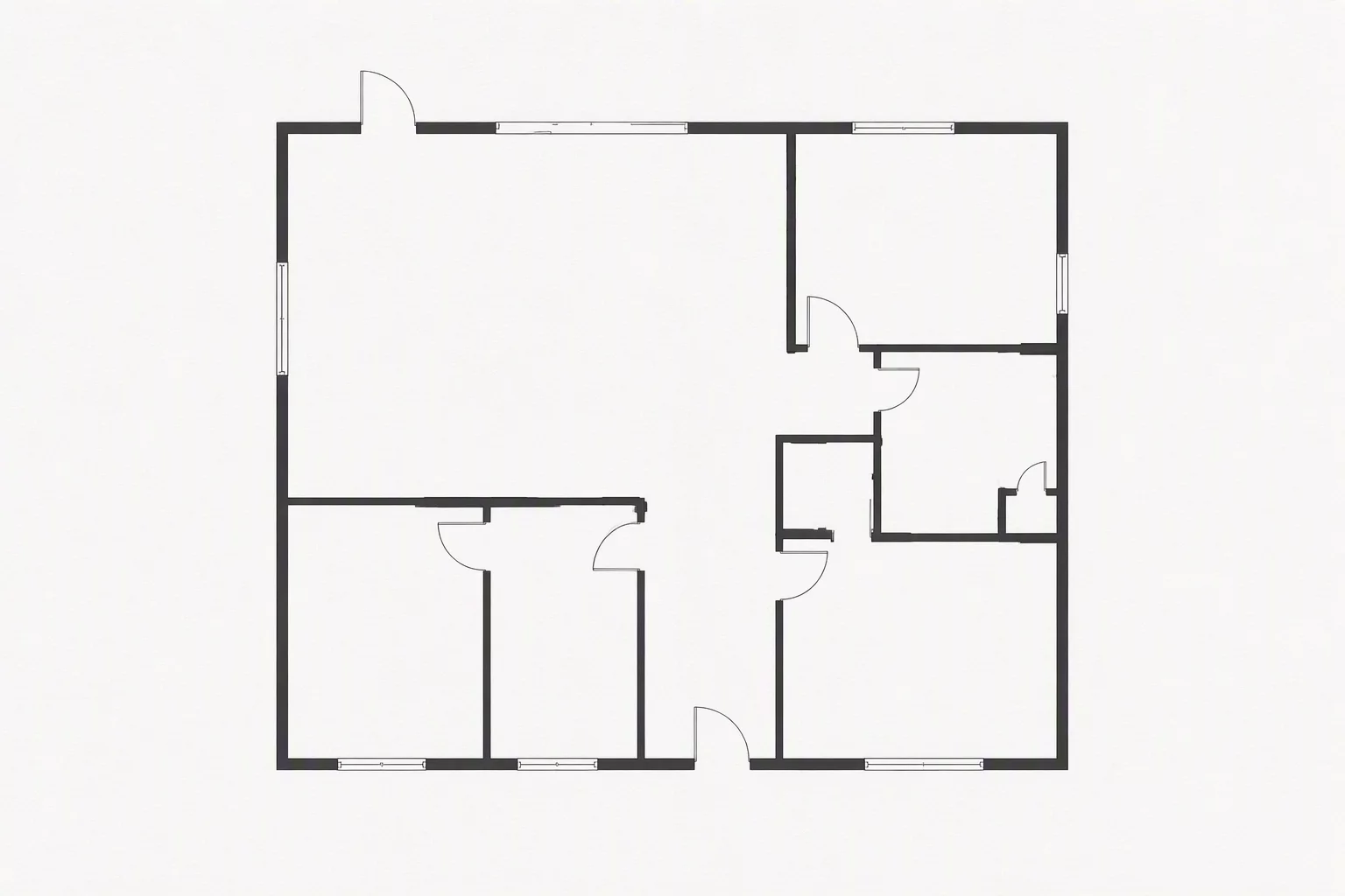 Drawing Strategy
Intentional Omissions in Plans
Learn why suppressing unnecessary graphic details is essential for producing clear and unambiguous architectural drawings.
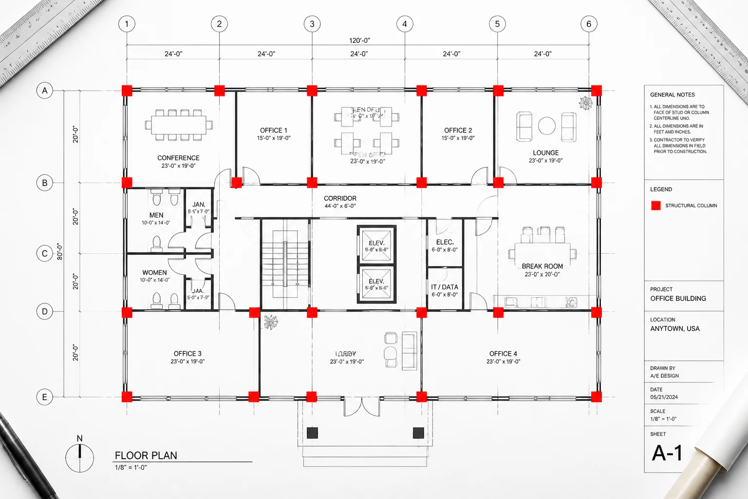 Graphic Clarity
Overriding Classes for Clarity
Using class overrides to emphasize critical structural boundaries and regulatory compliance elements.