Eliminating Floor Noise in Reflected Ceiling Views
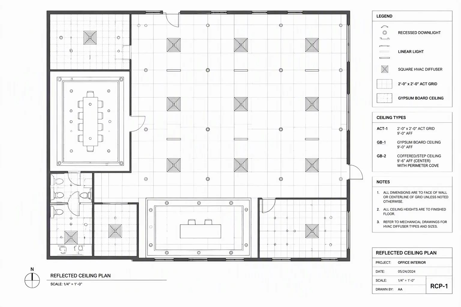
Reflected ceiling plans often suffer from visual contamination when floor-based objects, casework footprints, and door swing arcs remain visible. A contractor or electrical engineer reading an RCP needs immediate answers regarding ceiling grid coordinates, soffit transitions, luminaire placements, and device circuiting. Including floor finishes or low-height partitions in the same viewport creates visual friction and causes installation errors on site.
In Vectorworks, achieving a pristine reflected ceiling plan requires separating ceiling elements from standard architectural geometry using targeted class structures and viewport overrides. By turning off door swings, floor hatches, and non-structural floor elements, the sheet communicates the exact vertical and horizontal relationships of overhead components.
Essential Reflected Ceiling Viewport Rules
-
1
Intentional Layer Visibility: Display only structural boundary walls, ceiling grids, lighting fixtures, and high-level mechanical diffusers while hiding standard floor-level design layers.
-
2
Class Override Discipline: Set wall outlines to light gray linework so that ceiling grids, bulkhead steps, and lighting fixture symbols remain high-contrast.
-
3
Omission of Door Swings: Ensure door swing classes and hardware markers are turned off in RCP viewports to prevent confusion with ceiling break lines.
-
4
Dimensioning Reference Base: Pull all ceiling grid and lighting center dimensions strictly from primary structural column lines or finished wall faces rather than movable partitions.
"An effective RCP never competes with the floor plan; it looks strictly upward, mapping light, air, and ceiling heights with unambiguous precision."
Structuring Lighting and MEP Coordination
Coordination between electrical lighting symbols, recessed fixtures, and mechanical supply diffusers depends heavily on clean alignment. By locking ceiling grid origins directly to architectural reference points, field installers can position T-bar grids or drywall suspension channels without guessing layout offsets.
Annotations should indicate ceiling elevation transitions, cove lighting details, and sensor locations directly within the viewport annotation space. This keeps the design layer free of sheet-specific text while ensuring that any design modifications update the model geometry cleanly across all linked sheets.
Standardize Your Reflected Ceiling Sheets
Access comprehensive viewport setup templates, class override presets, and sheet intent guidelines for Vectorworks workflows.
Reflected Ceiling Plan Inquiries
Recommended Practical Cases
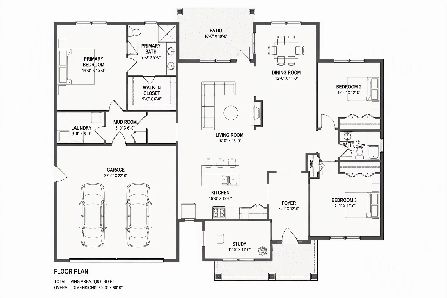 Floor Plan
General Floor Plan Execution
A practical look at setting up a general floor plan with clear hierarchy and clean annotations.
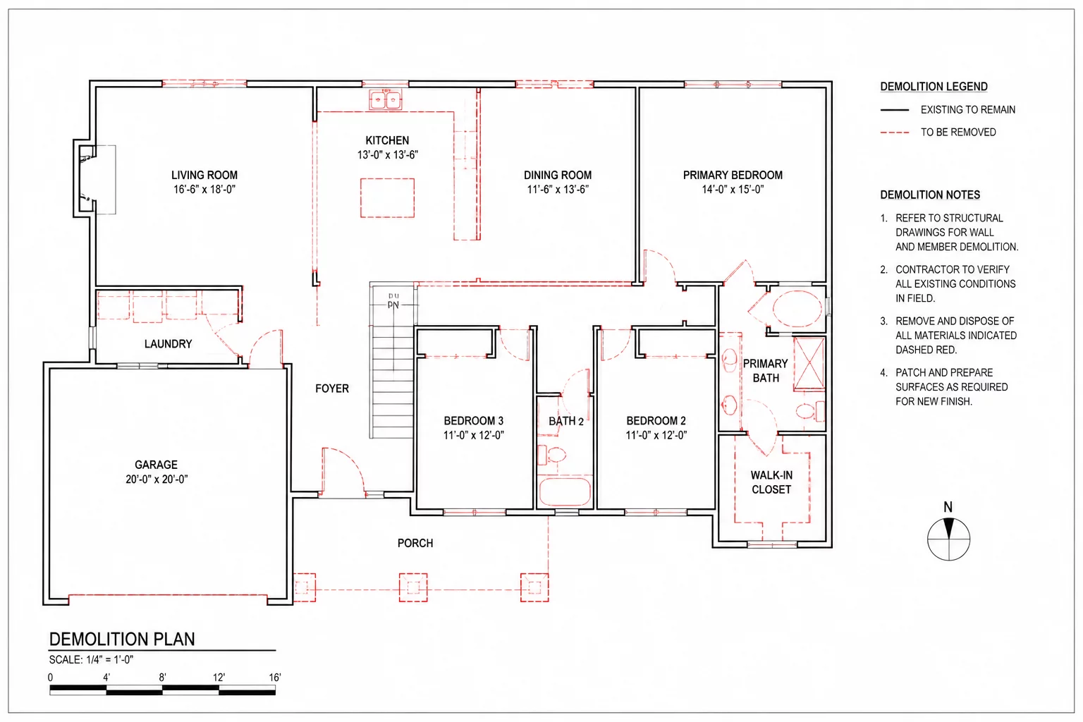 Demolition
Demolition Plan Clarity
Making demolition plans clear by hiding proposed work and highlighting removed elements.
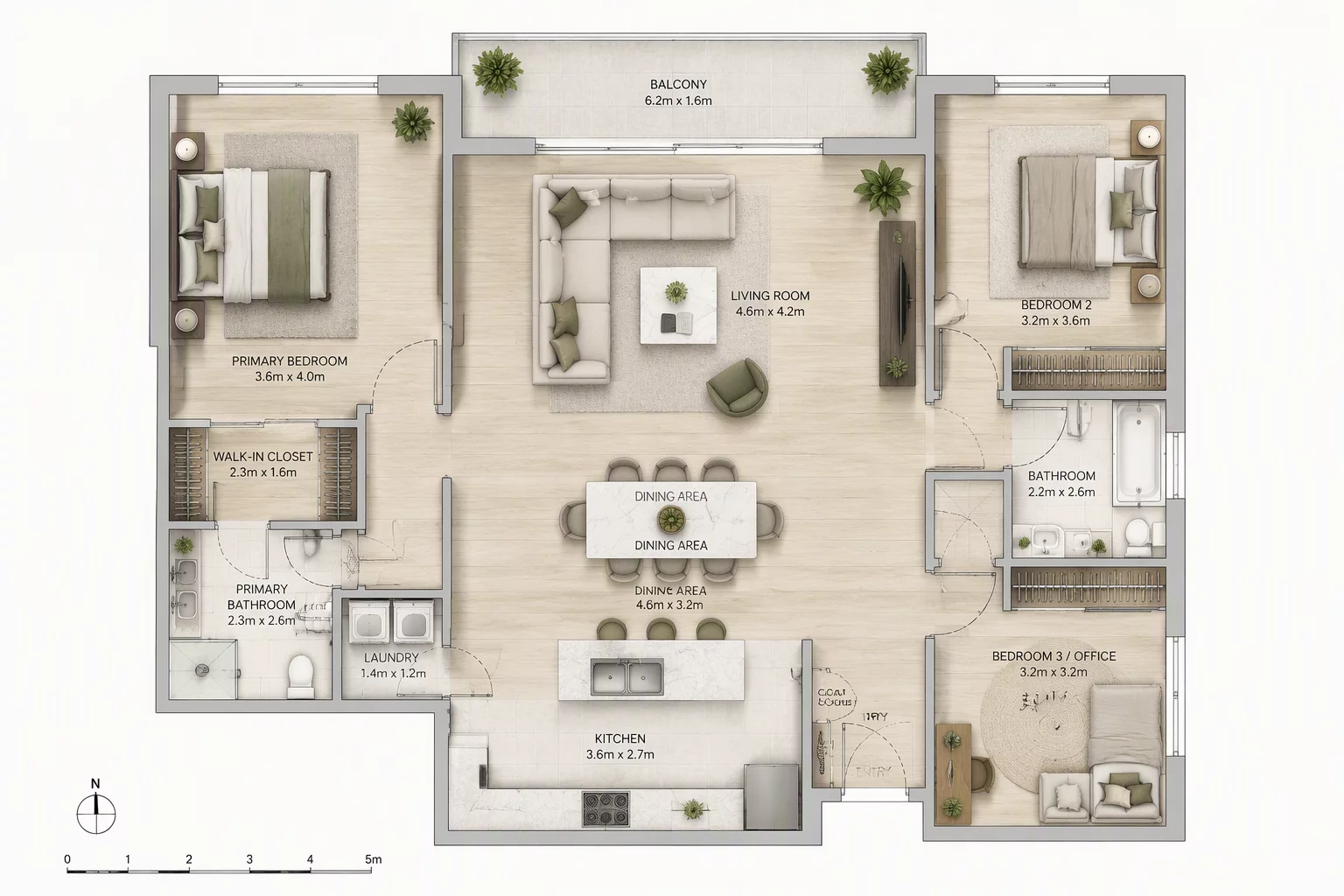 Interior Layout
Furniture Plan Hierarchy
Establishing visual hierarchy in furniture plans by subduing architectural boundaries.