
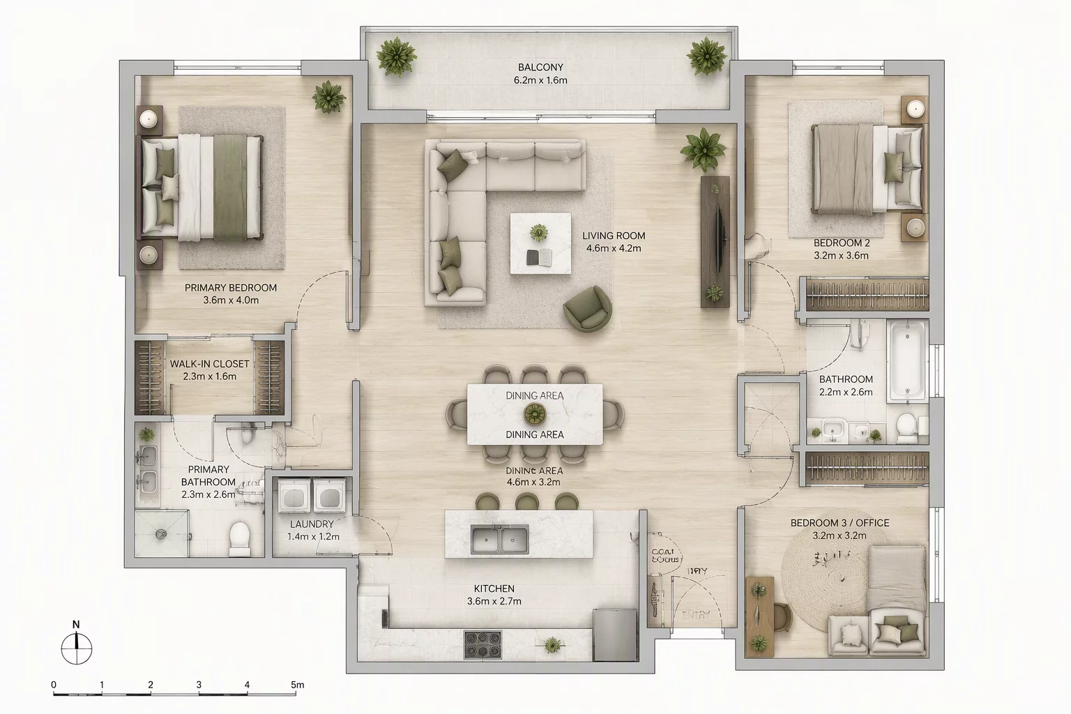
Defining the Purpose and Line Weight Logic
Furniture plans serve a dual role in documentation: they verify spatial ergonomics for clients while coordinating clearance envelopes and electrical feed locations for builders. When all line weights are drawn uniformly, furniture blocks compete with exterior enclosures and partition walls. A disciplined viewport setup suppresses wall hatching and architectural dimensions, letting secondary fixtures recede into subtle half-tone screen lines.
In Vectorworks sheet layer viewports, achieving this balance relies on targeted class overrides rather than manual drafting. By reassigning the pen weight of interior furniture symbols to crisp 0.13mm lines and toning down background walls with a 50% gray fill, the eye immediately identifies movement corridors, seating clusters, and key millwork elevations.
Core Principles of Furniture Plan Organization
-
1
Tone Down Partition Hatching: Wall fills should be set to solid white or faint gray in the viewport class properties so intricate chair legs and table geometries remain legible.
-
2
Standardize Clearance Envelopes: Circulation pathways require minimum 36-inch continuous clearance bands, represented using muted dashed bounding boxes on dedicated non-plotting classes.
-
3
Isolate Structural Grid Bubbles: Keep column centers and grid labels visible at sheet perimeters, but turn off interior wall dimensions to eliminate visual clutter.
-
4
Distinct Tagging for FF&E Schedules: Use hexagon or circular callout symbols containing sequential item keys linked to the Vectorworks master worksheet schedule.
“A successful furniture plan is not a decoration showcase; it is a technical tool that proves functional ergonomics, clearances, and electrical alignments.”
Layer Management and Class Override Setup
Setting up the sheet layer viewport starts with isolating design layer visibility. Deactivate ceiling fixture layers, plumbing rough-in notes, and demolition lines. Next, navigate to the Viewport Class Properties dialog. Here, assign all Furn- and FF&E- classes a defined pen color with high contrast against the floor slab while overriding the Wall-Interior class to a lighter gray stroke.
For electrical and data coordination, place power drops and floor box markers on a dedicated overlay class. This allows the same base layout to generate both an FF&E procurement drawing and a coordinated power-to-furniture installation sheet without duplicating 2D drafting geometry.
Refine Your Viewport Standards
Explore our comprehensive sheet cases to standardize class overrides, viewport annotations, and BIM coordination sheets across your Vectorworks firm library.
Frequently Asked Questions
Related Practical Cases
 Case Study
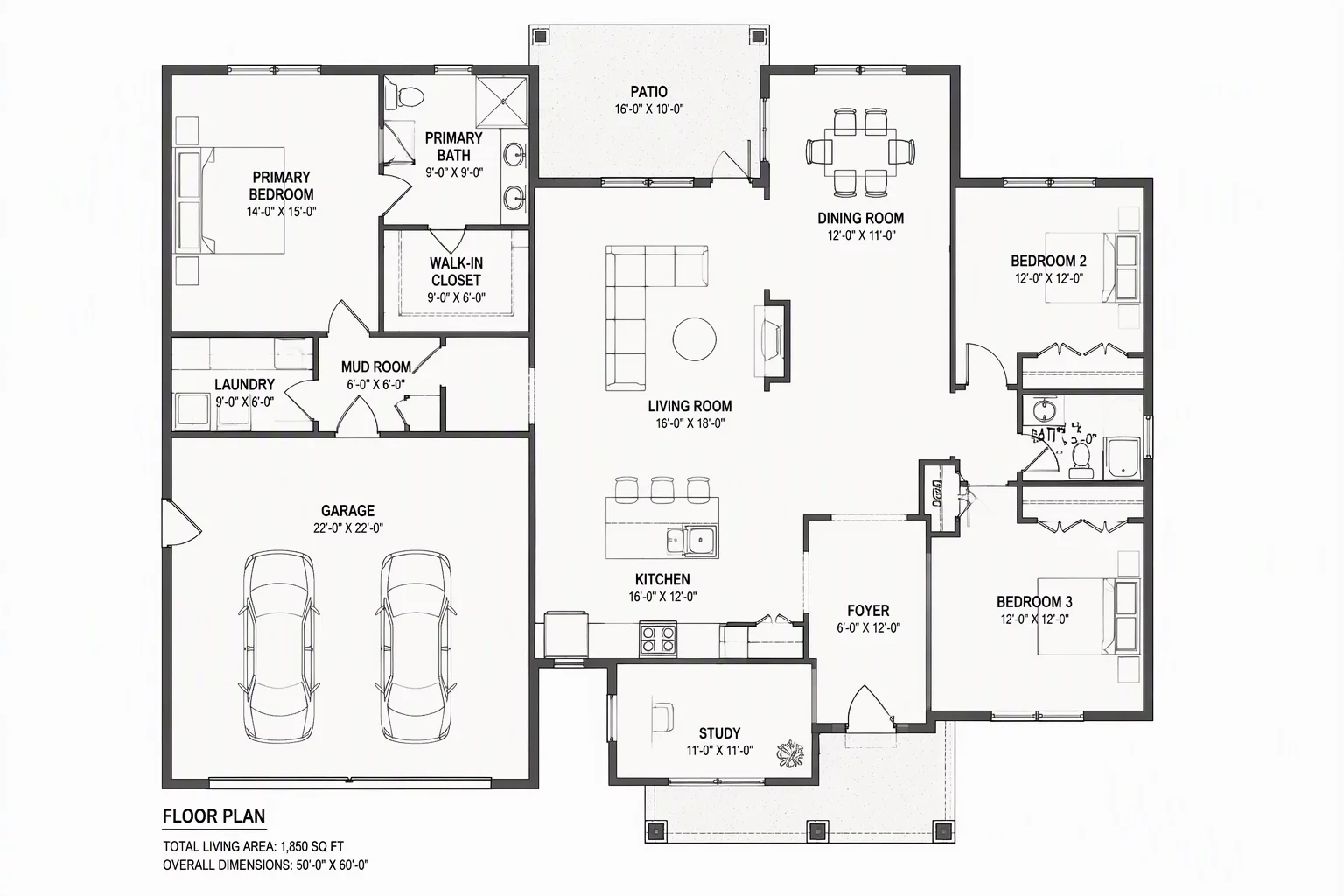
General Floor Plan Execution
A practical look at establishing hierarchy, dimensions, and partition tags on core architectural floor plans.
 Case Study
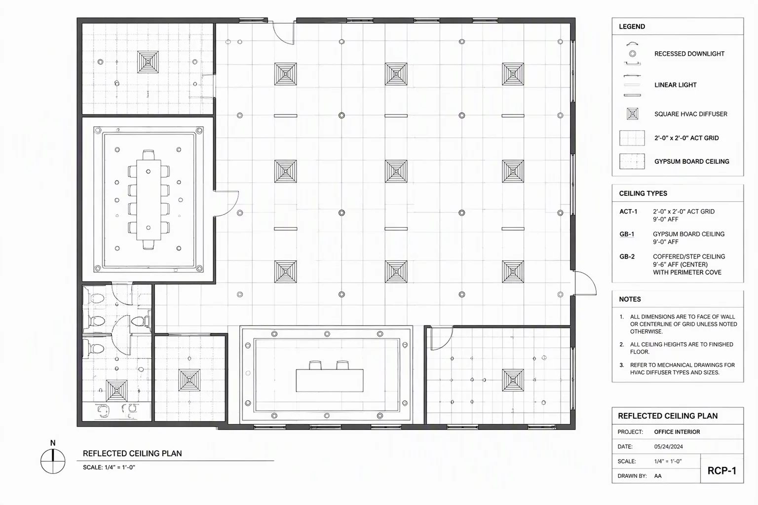
Reflected Ceiling Plan Focus
Focusing the RCP on lighting grids and mechanical diffusers while fading underlying partition geometry.
 Case Study
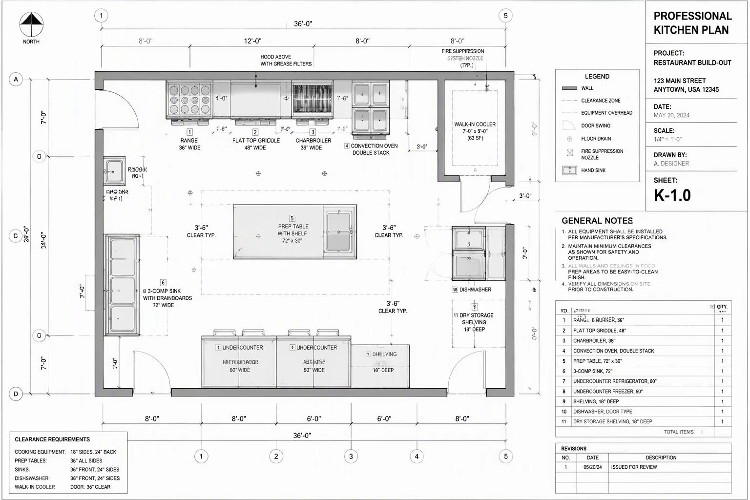
Enlarged Room Plan Details
Detailing enlarged room layouts with exact fixture clearances, cabinetry elevations, and contractor notes.