
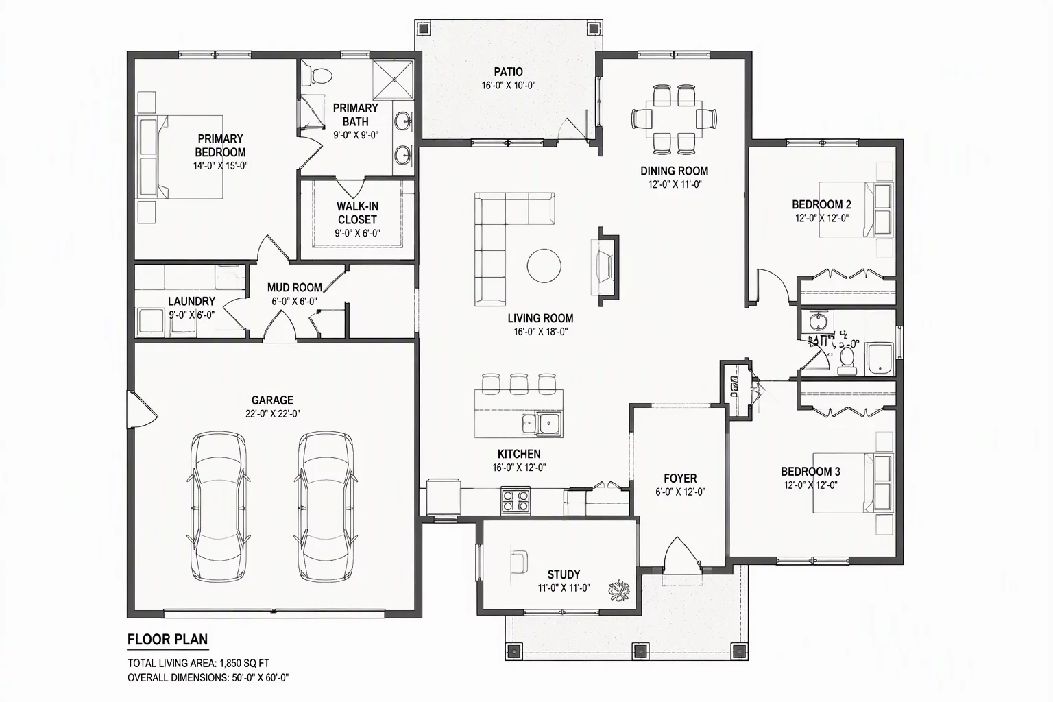
Isolating Primary Architectural Geometry
In Vectorworks architectural workflows, the general floor plan serves as the structural baseline for contractor coordination and permit review. Many project models suffer from viewport congestion when secondary assemblies—such as ceiling grids, mechanical chases, or loose furnishings—infiltrate the primary plan viewport. Isolating architectural boundary definitions ensures that wall compositions, door swings, and primary vertical access routes immediately communicate intent.
Applying intentional class structures allows project teams to control lineweight hierarchy across diverse wall types. Outer masonry envelopes receive prominent heavy profiles, whereas interior non-bearing partitions remain subtle. By dedicating the general floor plan to fundamental spatial boundaries, field builders immediately extract dimensions and room tags without parsing irrelevant finish schedules.
Core Implementation Benchmarks
-
1
Baseline Scale: Standardize at 1/4" = 1'-0" (1:50 metric) to ensure legible dimension strings and door callouts across standard ARCH D sheet formats.
-
2
Visibility Control: Explicitly turn off furniture, electrical, reflected ceiling, and demolition classes inside the primary sheet layer viewport.
-
3
Class Overrides: Override wall cut lines to 0.35mm solid black with a 15% grey pouché fill to separate solid structure from circulation zones.
-
4
Annotation Space: Place room names, ceiling heights, door IDs, and exterior boundary dimensions strictly within the sheet layer viewport annotation space.
"A drawing that attempts to show every fixture and finish invariably answers no single question well. The general floor plan must master spatial boundaries above all else."
Disciplined Dimensioning and Viewport Coordination
Dimension strings demand hierarchical placement to prevent collision with interior millwork callouts. Exterior strings must follow a three-tier hierarchy: overall building footprint on the outer string, major structural grid offsets on the middle string, and window or door opening centerlines on the innermost string. This uniform rhythm allows structural trades and framing crews to rapidly cross-verify structural baselines.
Utilizing viewport crop tools along coordinated structural column grids keeps plans consistent across multi-story buildings. Maintaining shared design layer elevations while decoupling annotation text inside individual sheet layer viewports prevents accidental global displacement when adjusting local sheet layouts.
Standardize Your Viewport Workflow
Download our Vectorworks view intent class template and review sample sheet setups for multi-story residential and commercial plans.
Frequently Asked Questions
Related Practical Case Studies
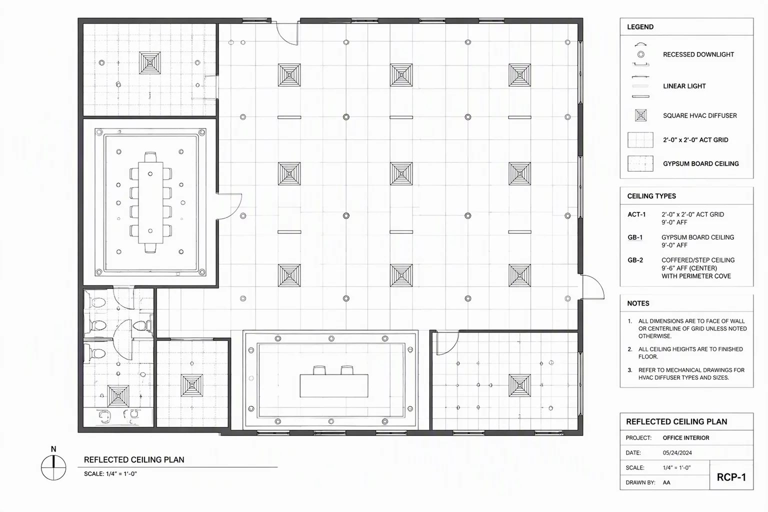 Case Study #02
Reflected Ceiling Plan Focus
Focusing the RCP on lighting and ceiling elements while eliminating floor-level noise.
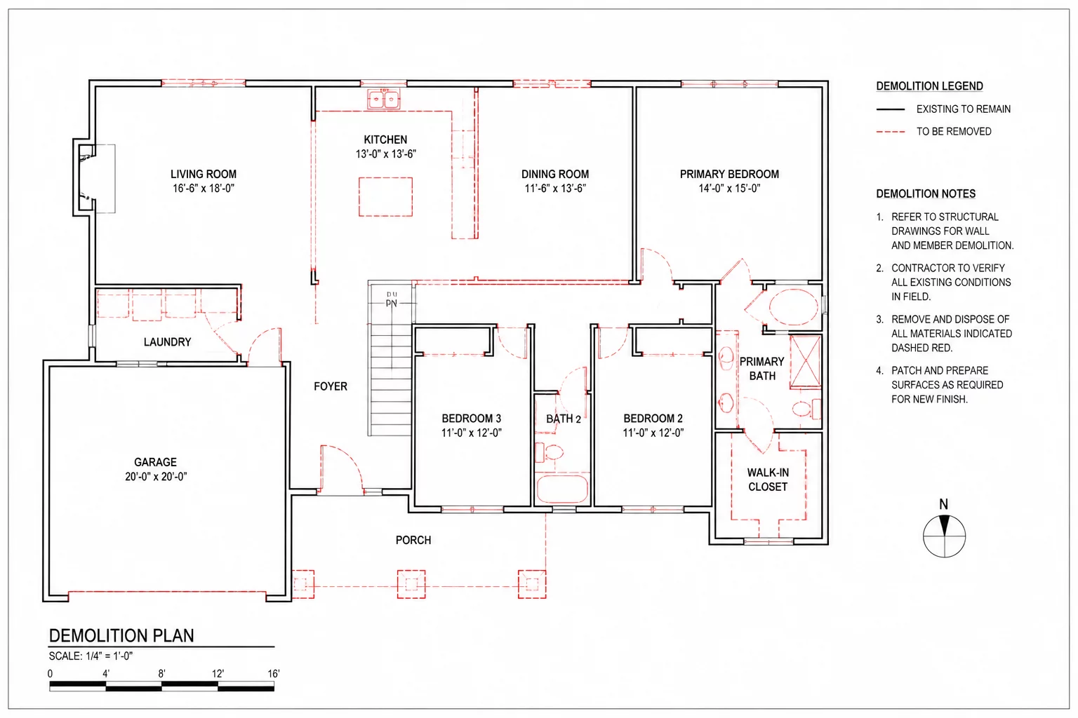 Case Study #03
Demolition Plan Clarity
Making demolition plans clear by hiding proposed work and highlighting removals.
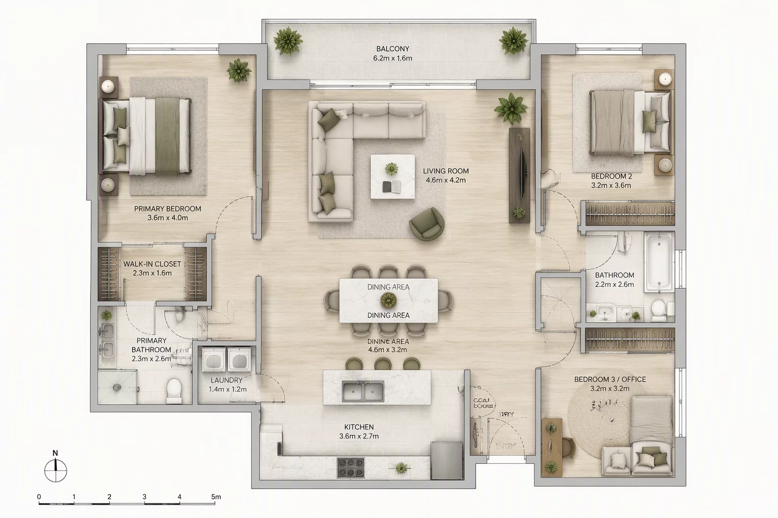 Case Study #04
Furniture Plan Hierarchy
Establishing visual hierarchy in furniture plans through muted architectural backdrops.