
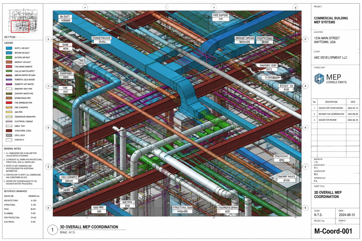
Isolating Conflicting Disciplines in Single Viewports
Interdisciplinary coordination sheets frequently collapse under the weight of competing graphic weights. When ductwork, conduit runs, plumbing risers, and structural steel beams share the same viewport as architectural partitions, contractors and consultants struggle to identify spatial conflicts. Setting up a dedicated coordination sheet requires deliberate graphic de-escalation of background elements and calculated high-contrast overrides for active systems.
Rather than exporting disparate DWG overlays that lose reference coordinates, the Vectorworks referenced viewport workflow consolidates live design layers. This setup allows project teams to isolate spatial conflicts before site mobilization, turning the coordination drawing into a decisive conflict-resolution instrument.
Core Principles of Multi-Disciplinary Coordination
-
1
Reference Hierarchy: Architectural background walls and slabs are assigned a 50% gray fill with thin 0.13mm lines, creating a legible neutral canvas for active trade routes.
-
2
Trade Color Distinction: MEP trades receive dedicated class color overrides: magenta for fire protection, cyan for HVAC supply/return, orange for electrical feeders, and yellow for domestic plumbing.
-
3
Vertical Clearance Offsets: Section viewports cut along critical service corridors verify ceiling plenum clearances and eliminate penetrations through structural beams.
-
4
Intentional Annotation Rules: Only clash callouts, invert elevations, and coordination tags are visible on this sheet layer, eliminating standard room finish and furniture callouts.
"A coordination sheet does not prove that systems fit in theory; it confirms that trades will not fight for the same physical cubic inches in the field."
Step-by-Step Viewport Layer and Class Overrides
Begin by duplicating your base floor plan viewport onto a dedicated coordination sheet layer (Sheet SD-501). Access the Viewport Classes dialog and override the Pen and Fill attributes of all architectural envelope classes (A-WALL, A-DOOR, A-GLAZ). Shift their fill to solid white with a 40% opacity or uniform light gray line weight. This instantly recesses architectural context behind MEP trade layers.
Next, turn on external consultant references under Design Layers. Ensure the structural grids align perfectly to avoid spatial displacement. Set consultant classes (M-DUCT, P-PIPE, E-CABL) to solid saturated hues with 0.35mm lineweights. If tight vertical tolerances exist in double-height spaces, place a linked section viewport beside the main plan view to answer clearance questions without switching sheets.
Master Purpose-Driven Viewport Configuration
Discover our complete library of Vectorworks view intent cards, guiding class hierarchies and layer visibility for every architectural phase.
Frequently Asked Questions
Practical Architectural Case Studies
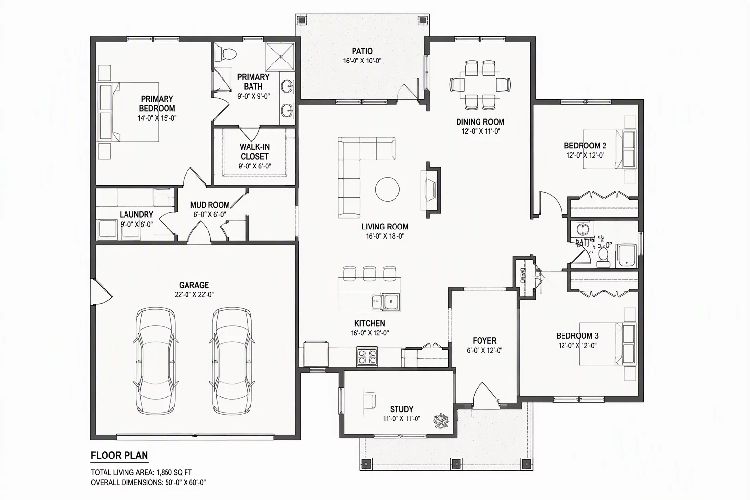 Case Study #01
General Floor Plan Execution
Setting up comprehensive floor plans with optimal hierarchy, partition weights, and room relationship data.
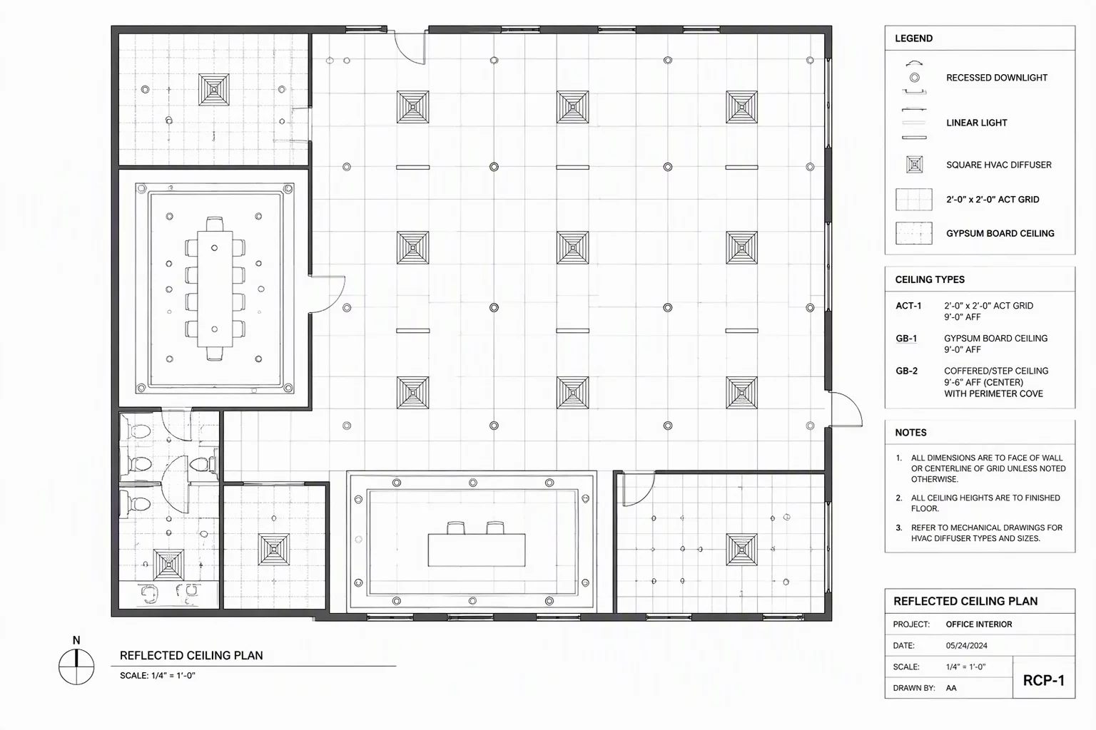 Case Study #02
Reflected Ceiling Plan Focus
Filtering ceiling grids, bulkheads, and lighting fixtures while keeping lower wall assemblies subdued.
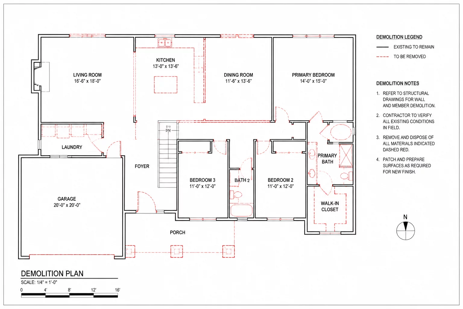 Case Study #03
Demolition Plan Clarity
Techniques for isolating existing elements, scope of removal, and salvage boundaries without visual confusion.